M21D 71M 2d 0.55 kW – 3000 rpm Specifications M21D 71 M 2d Strength –…
Gamak electric motor
History of Hamak Company
- It was established in Türkiye in 1961
- It is active in the field of electric motors, generators and wind turbines.
- The establishment of this company reduced a major part of Türkiye’s imports in this field.
- Power from 0.06 to 3000 kW
- Gamak electric motor produced with IEC standard
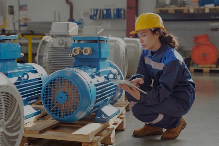
Gamak electric motor
Gamak electric motor with permanent magnet as a toy
Gamak electromotor converter is an (electromechanical electric machine) that converts electrical power into mechanical power. In conventional electric motors, current-carrying coils create magnetic fields that convert attractive and repulsive forces into motion. Therefore, the Gamak electric motor is the counterpart of a similar generator that converts kinetic energy into electrical energy. Electric motors usually create rotary motions, but they can also be made for translational motions (linear motion). Electric motors are used to drive many equipment, machines and vehicles.
Gamak electric motor list
- 1 story
- 2 basic principles/functions
- 2.1 Terms
- 2.2 DC motor (commutator motor)
- 2.3 AC and three-phase motors
- 3 types of Gamak electric motors
- 3.1 Rotating and mobile field machines
- 3.2 commutator or commutator machine
- 3.3 Sonstige
- 4 applications
- 4.1 Electric motors in mobile applications
- 4.2 Applications in industry
- 5 Effectiveness and efficiency
- 6 Production of electric motors
- 6.1 Housing construction
- 6.2 Production of multilayer cores
- 6.3 Fertigung des Stators
- 6.4 Shaft construction
- 6.5 Fertigung des Rotors
- 6.6 End of assembly
- 7 literature
- 8 See also
- 9 web links
- 10 individual proofs
The story of Gamak electric motor
Andreas (Andrew) Gordon, a Benedictine monk until his death in 1751, experimented with electricity and invented a horizontally rotating metal star that rotated when electrostatically discharged. The power source was a Leyden bottle. As a professor at the University of Erfurt, his publications were noted and circulated among researchers, but sometimes without naming the inventor.
, Danish physicist and philosopher, in 1820, Hans Christian Oersted discovered the magnetic effect of electric current, which is a fundamental phenomenon of electromagnetism. A year later, Michael Faraday published the results of his work on “electromagnetic rotation”. He constructed a device in which an electric conductor revolved around a fixed magnet, and in a reciprocal experiment, a moving magnet revolved around a fixed conductor. In 1822, Peter Barlow developed what was named after him the Barlow wheel. British scientist William Sturgeon invented another engine precursor in 1832. [1] In continental Europe, Ennius Jedlik (1827) and Hermann Jacobi worked on further development of the Gamak DC electric motor. As early as 1834, Jacoby developed the first practical Gamak electric motor in Potsdam, and in 1838 in St. Petersburg he equipped a twelve-person boat with his 220-watt motor, [2] which also represented the first practical application of the Gamak electric motor. . . American blacksmith Thomas Davenport also developed a commutator motor in Vermont. He received a patent for his design on February 25, 1837.
Thus, around 1837/1838, the basis of a Gamak electric motor was known and also became a machine suitable for use. Werner von Siemens patented his dynamo machine in 1866. For the first time, it made it possible to produce electrical energy on a larger scale. This helped the Gamak electric motor to achieve a breakthrough for practical and widespread use. At that time, there were also some technical developments of various types of electric motors, which ultimately did not become important. These include the Gamak electric motor developed by Egger, which is similar to the steam engine, and the “Gamak electric motor cycle” developed by Johann Kraugel in 1867.
-

“Barlow’s Wheel” (1822)
-

Engine Jedlik (1827)
-

My “Magnetic Electric Machines” circa 1890
-

“Magnetic Electric Machines” II around 1890
Since around 1880, power grids and power plants have been built in many countries. For example, in Germany, Emil Ratnau was a pioneer with his Allgemeine Electricitäts-Gesellschaft, and in America, Thomas Alva Edison was a pioneer. With the provision of large-scale electric power, the Gamak electric motor expanded rapidly. Along with chemical industries, this electrification was the most important feature of the second industrial revolution. Public trams, which were replaced by electric horses, were pulled by streetcars, and in industry, electric motors were used instead of steam engines to drive various machines.
Basic/functional principle of Gamak electric motor
Polarity of the rotor magnetic field in a DC motor with a permanent magnet stator
The rotational movement of a Gamak electric motor is based on the attraction and repulsion forces that several magnetic fields exert on each other (Lorentz force). In a typical Gamak electric motor, there is a fixed outer part and an inner part that rotates inside. Either one of them has permanent magnets and the other has an electric coil, or both components have coils. Each current-carrying coil produces a magnetic field whose direction (north pole/south pole) depends on the direction of the current – if the current flows through the coil in the opposite direction, the magnetic field will also reverse. The continuous rotation of the inner part is achieved by continuously changing the current direction or “polarity reversal” of the coils during rotation.
regulation
- Stator
- The fixed and magnetically effective part of a Gamak electric motor is called the stator. In electric motors, the stator is usually outside and connected to the housing. If the stator is inside, the motor is called “external rotor”. The stator housing usually carries mechanical fasteners as well.
- rotor
- The magnetically actuated moving (usually: rotating) part of a Gamak electric motor that turns the motor shaft. If the armature is not a permanent magnet, it consists of a shaft, an armature and a coil.
- anchor
- The iron core of the rotor around which the rotor winding(s) are wound.
- Bar shoes
- A shoe-shaped protrusion in the iron of a magnetic core, intended to direct the magnetic field to this point.
- replacement
- A disk with electrical connections that are parts of the disk. The disk rotates with the rotor axis. The coils are connected to the terminals. The commutator disc reverses the polarity of the coils during one revolution. The detailed functionality is explained in the following section.
DC motor (commutator motor)
the rotor of a commutator motor; Carbon brushes and stator are removed
(Fixed) In a DC motor, the stator can be a permanent magnet with pole shoes, but external excitation via an exciter coil instead of a permanent magnet is also possible. On the other hand, in the case of AC commutator motor or universal motor, there is always an excitation winding in the stator. If current passes through this coil, an excitation field (magnetic field) is created (Ørsted principle).
Inside the stator, there is a rotor, which in most cases consists of a coil with an iron core (the so-called armature), which is installed in a rotating manner in the magnetic field between the shoes of the stator poles.
The current for the armature is divided by a commutator
and sliding contacts (carbon brushes) are provided. If current is sent through the rotor, a magnetic field is created here as well, which now interacts with the magnetic field of the stator. It therefore rotates around its axis and always switches the appropriate windings through the commutator to the current path with which it rotates and thus can convert electrical work into mechanical work.
If such a motor did not have a commutator, the armature would rotate until the rotor magnetic field aligned with the stator field. In order not to stop at this “dead point”, the current in the armature windings is switched with the help of a commutator (also known as a commutator or collector) for each new part. The commutator consists of metal parts that form a cylindrical or circular surface that is interrupted by thin strips of non-conductive material (plastic, air). Armature windings are connected to sections. On the commutator are pressed by springs, usually two carbon brushes that supply the current. With each rotation of the rotor, the direction of the current changes from the armature coils of the Gamak electric motor, and those conductors whose current flow is directed in such a way that the torque is created enter the magnetic field of the stator.
The magnetic field in the rotor is constant relative to the stator.
Therefore, the iron core of the rotating armature must be composed of layers to prevent eddy currents from the stack.
AC motors can also be built on this principle if the excitation field also changes its polarity with alternating current (universal motor). Then the stator must also consist of a multi-layered core.
Gamak AC and three-phase electric motor
Three-phase asynchronous motor with squirrel cage rotor and 750 watt power
With alternating current, if the number of turns follows the rhythm of alternating current, a commutator can be omitted. Then the rotating magnetic field of the rotor is created:
- induced by the excitation field through the induced currents in a short circuit winding (asynchronous motor)
- By magnetizing an iron core with a pole (reluctance motor, stepper motor)
- by permanent magnets (stepper motor, DC motor with electronic commutation, synchronous motor)
- by an electrically excited rotor (see e.g. magnet wheel or excitation systems for synchronous machines)
Therefore, such motors have little or no starting torque. You need help getting started, but you can also start with AC with more than one phase:
- Three-phase motors operate with three-phase current, which consists of three alternating voltages that change phase by 120 degrees and thus create a rotor. Square
- Shaded pole and capacitor motors produce an auxiliary phase (rotating field) for starting from single phase alternating current.
- Stepper and reluctance motors operate with variable frequency alternating current and/or with multiple phases to “keep on running” and no step losses occur.
- Synchronous motors require start-up assistance or self-oscillating “in phase”.
Types of Gamak electric motors
Winding with insulating bands in a large Gamak electric motor
Rotary and mobile field machines
- Three phase motor
- Asynchronous three-phase device
- Slip ring motor
- Three-phase synchronous machine
- Waterfall device
- stepper motor
- Brushless DC motor
- Asynchronous three-phase device
- Linear motor
- AC motor
- Capacitor motor
- Split bridge engine
- Synchronous motor / Einphasenasynchronmotor
- Reluctance engine
- Magnet motor
- Transversal machine
Gamak electric motor current inverter or commutator device
- DC motor
- Universal motor (for direct and alternating current)
- Repulsion engine
- Permanent magnet DC motor
- DC motor with electric excitation (separately excited).
- Series engine
- Shunt device
- Compound engine
This technology left elsewhere
There are some types of electric motors that are not of commercial importance today.
- Engine bearing
- Single pole machine
- homopolar motor
- Barlow Rod
Electrostatic motors use electric fields created by loads instead of magnetic fields. However, due to high voltages and lower efficiency levels, these motors are only suitable for small powers and scales.
Application of Gamak electric motor
Different electric motors, with 9V battery for size comparison
Electric motors are used both uncontrolled and controlled. In simple cases, unregulated three-phase motors with star-delta switching are used. However, these are only suitable for solving primary drive tasks. In most cases in today’s practice, there are more difficult drive problems, such that electric motors must be controlled by a controller. If more power is required, electronic power actuators must still be placed between the control system and the Gamak electric motor . When the Gamak controller and electric motor meet and form a functional unit together, it is called “electric drive”. Therefore, a Gamak electric motor does not depend on a regulation in itself. However, in many practical cases, their interaction has been beneficial.
Gamak electric motor in the past
Electric motors first found practical use as a means of driving trams, and somewhat later as a universal drive to replace steam engines in factories, and for this purpose were used by means of belt drives to move electric looms and the like. would be With the introduction of assembly lines in industry, electric motors became the driving force for entire branches of industry.
In the field of transportation and handling, electric motors were first used in electric locomotives and electric trains and later in electric carts and forklifts. With the further development of batteries, today electric cars with greater Gamak electric motor ranges are made and due to the high efficiency of the electric drive, they are considered as a replacement for the combustion engine in the future. Developments in power electronics further increased the application – since then, maintenance-free asynchronous motors can also be used for variable speed drives.
Today, Gamak electric motors are widely used in cars, automata, robots, toys, household appliances, electronic devices (such as video recorders, hard drives, CD players), fans, lawn mowers, cranes, etc. The great importance of the Gamak electric motor for today’s modern industrial society is also reflected in energy consumption: electric motors account for more than 50% of electricity consumption in Germany.
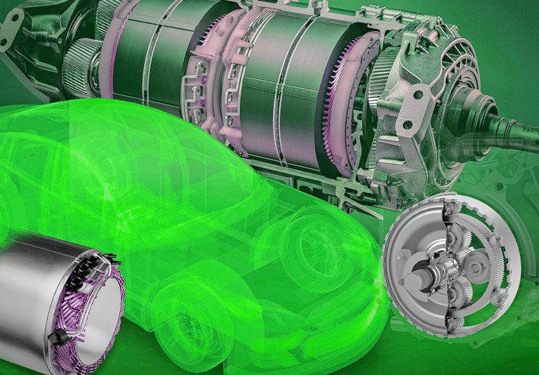
Gamak electric motor in transportation applications
Electric motors have long been used in motor vehicles and trains. The reasons for this are:
- High efficiency (especially in partial load operation, important for battery performance),
- Uninterrupted torque delivery across the full speed range, without the need for launch synchronization or changeable gear ratios. This means high driving comfort (also important for electric wheelchairs, for example).
- Smaller size and mass than a comparable internal combustion engine; This allows for space-saving installation directly near the wheels.
- no release; Therefore, it is possible to use in emission-sensitive areas (for example, workshops, tunnel areas and residential areas).
- Lower running costs (extremely long engine life, less maintenance).
- Simple structure including simpler cooling system.
- Installing an electromotor brake that allows regenerative braking does not require maintenance by recovering energy and due to wear, as is the case with conventional braking systems.
Despite these advantages, the Gamak electric motor has not been widely used in cars and trucks. The reason is especially the limitation of the maximum range or the high mass of energy storage (accumulators) and their long charging time.
Some model airplanes (electric flight), small ships, torpedoes and submarines are also powered by the Gamak electric motor and an accumulator. The electric motors of other submarines are powered by small fuel cells on board or by a nuclear power plant on board.
Vehicle propulsion concepts with electric motors, but without or only partial energy storage in an accumulator, are:
- Fuel cell drive: for example, one of the projects is HyFLEET:CUTE, which is a continuation of the CUTE project. There are problems with the lifetime and costs of fuel cells.
- Hybrid drive (like Toyota Prius): a gasoline engine combined with an electric motor/generator and with accumulators (advantages of partial load range/urban performance, high driving comfort, regenerative braking recovery ( ), buffering with double layer capacitors).
- Gyro drive: flywheel with a generator that drives the traction motors acting as energy storage (used in gyro buses, e.g., short range, regenerative braking possible).
In the case of electric trains and electric cars, electrical energy is supplied by overhead lines or conductor rails. Regenerative braking can also be done here if the supply network is designed for this or if accumulators are installed. Double layer capacitors are also used here.
Another application of mobile is diesel-electric engine. Here, a diesel engine generates electricity that drives the traction motors. Regenerative braking is not possible unless additional accumulators are carried. Diesel-electric drives can be found on ships, locomotives, and submarines (complemented here by an accumulator).
Applications of Gamak electric motor in industry
The different areas of application of electric motors in the industry can be divided into twelve areas. The first four deal with material flow. The next four with continuous or hourly production lines and the last two with processes that operate on the workpiece.
- Conveyor belt drives: The demand for drives is long life, robustness and reliability, low maintenance costs, high modularity and low energy consumption. Drives are usually used in continuous operation, so acceleration plays a secondary role.
- Traveling drives are used in vehicles for transporting materials, for example in driverless transport systems, gantry cranes, storage and retrieval devices or electric monorails. A high level of drive precision is required for precise positioning.
- Lift drives are intended to transport goods vertically upwards. Gamak electric motor includes cranes, lifting tables, freight elevators and construction elevators.
- Positioning drives are used to move individual goods from one point to another. This includes the assembly of electronic components, feeding and removal of workpieces in production machines and assembly machines. Most of these drives are designed as direct linear drives.
- Synchronous Drives for Robots: Industrial robots often have up to six axes that must have a specific target position at the same time while moving. Therefore, it is necessary to coordinate the individual drives in order to create the desired movement of the robot arm.
- Synchronous drives are used in manufacturing processes where a product is produced continuously as an endless material. This includes transport, rolling, coating, winding and winding as well as printing.
- Coil drives are often at the beginning or end of continuous current generation. For example, it is used in steel mills to inflate sheet metal into coils, and in mechanical engineering and the automotive industry to unwind them again. Other examples are winding and unwinding of wire, thread or paper. As Gamak motors get bigger and bigger over time, the peripheral speed increases while the speed remains constant. In order to avoid product tearing, the drives must be controlled on the environment of the wound material.
- Clock drives for cross cutters and scroll saws are used in continuous production to separate flowing material, for example by sawing a section. Special requirements arise from the fact that the material moves during the cutting process.
- Camera drive electronics are drives with non-uniform motion. For example, a punch tool should be lowered slowly to achieve good work quality on the workpiece and raised quickly. Other uses include glue, welding, bending and cutting.
- Drives forming processes: This includes steel sheet pressing, plastic extrusion, deep drawing or drop forging.
- Main drives and tools in machine tools. They are used to drive milling, drilling and turning machines. It is the only industrial use case for which there is a rich engineering literature.
- Drive for pumps and fans.
The effectiveness and efficiency of Gamak electric motor
Technologically obsolete electric motors lead to increased energy consumption. [14] In 1998 a voluntary agreement was reached between the European Section Committee for Electric Drives CEMEP and the European Commission. In this outdated contract, three performance classes were defined:
- EFF3 = low efficiency motors
- EFF2 = Engines with improved efficiency
- EFF1 = motors with increased efficiency
In 2009, a new global standard for efficiency classes (EN 60034-30:2009) was introduced. The following efficiency classes are valid today for low-voltage three-phase asynchronous motors in the power range from 0.75 kW to 375 kW: [15] [16]
- IE1 = standard efficiency (compared to EFF2, limited sales authorized as of June 2011)
- IE2 = high efficiency (compared to EFF1)
- IE3 = superior efficiency
- IE4 = Super Premium (> 97% realized) [17]
- IE5 = Ultra Premium [18]
As of June 16, 2011, uncontrolled motors (0.75-375 kW) are only available on the market from power class IE2. The proportion of highly efficient engines should be steadily expanded. For example, permanent excitation synchronous motors have the highest efficiency levels. [17]
As of July 1, 2021, uncontrolled motors (0.75-375 kW) will be marketed only from power class IE3.
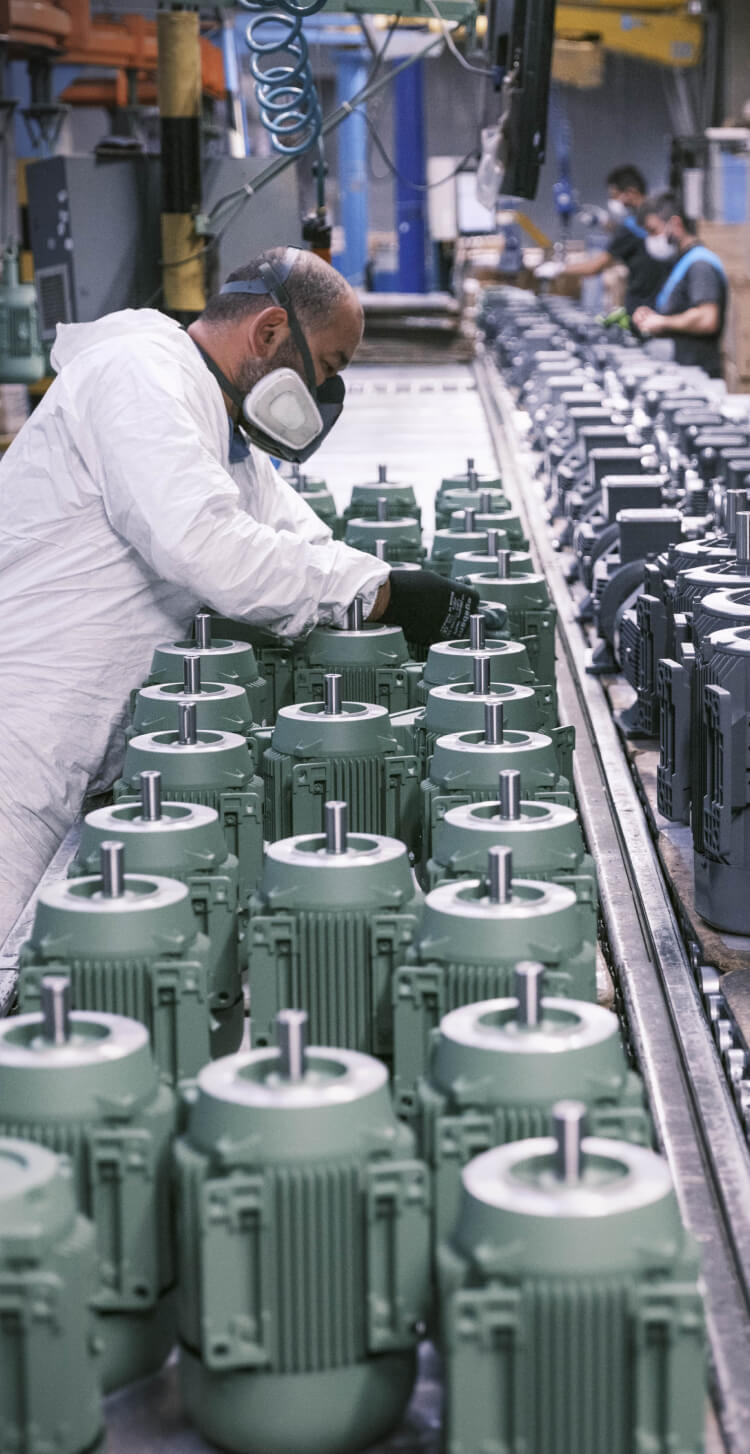
Making electric motors
Each component of the Gamak electric motor is made independently of each other. The most important of them are housing, stator, shaft and rotor. Then the final assembly is done.
Making Gamak electric motor
The actual housing is closed on both sides by covers, which in the case of electric motors are known as end bearings, because they are used to shield the motor shaft with . However, the individual process steps are the same for the end shields and housing. Both are first roughly shaped by casting or extrusion, followed by fine machining by turning, drilling and grinding, and finally cleaning. Details depend on the number of parts produced.
Sand casting is used only for small quantities, for example in the manufacture of prototypes. For medium and large quantities, it is suitable for die casting and centrifugal casting as well as extrusion. Diecasting is the most common process with a share of 60%. Here the mold is made of steel and can be cast about 80,000 times. The cost of the machines required is between 700,000 Euros and 1 million Euros, so a minimum amount of around 15,000 should be obtained to be cost-effective. Centrifugal casting systems, on the other hand, only cost around €60,000 to €100,000. The most expensive extrusion presses are 8 million euros. So they are only suitable for very large series, but have the lowest unit cost. [22]
After casting or extrusion, the chambers are emptied. Most fine machining is usually done in machining centers that specialize in turning, drilling, milling, and grinding. These tasks include internal contour turning, precision machining of edges and drilling of paths or threads.
In small series, the chamber is usually cleaned by blasting it with dry ice (so-called dry ice blast) or with small balls (shot blast). This removes casting residues, chips, dust and other dirt particles. The medium series are cleaned using an ultrasonic bath. Continuous cleaning systems are used for large series that include loading station, cleaning and washing areas, drying area and transfer station.
Gamak electric motor sheet packaging production
The actual components of the power generator, namely the rotor and stator, are assembled from multilayer cores. Laminate cores have the advantage of preventing eddy currents compared to all-material construction, thus increasing efficiency. When assembling sheets in stacks, it is important to avoid short circuits. Therefore, individual sheets are covered with an insulator. They are made of electrical steel. These are steel sheets containing silicon that have improved magnetic properties. Since its production is very complicated, it is bought by Gamak electric motor manufacturers. Sheet metal packages are produced in several steps: cutting sheets, stacking, permanent connection (gluing, welding, etc.) and reworking.
For smaller series or prototypes, the sheet metal is removed using a laser or water jet cutter. Punching is more economical for larger series. Then the sheets are stacked. With punching, this can be done directly in the machine, while with other methods an additional process step is required. There are several options for connecting multilayer cores. In mass production, blades on individual sheets are often pressed into recesses in the underlying layers. This step is often integrated directly into the punch. After stacking, individual layers can also be welded together. This is cost-effective with much smaller amounts, but has the disadvantage of creating an electrically conductive junction that causes eddy currents to form. Since the welds can be placed in places where the magnetic field is not important, the performance penalties are small. Another option is to use baking varnish. Here, after punching, each sheet is covered with baking varnish and stacked and then baked in the oven. As a result, the layers stick together on one side and separate on the other side.
As a final step, post-processing can be done to increase the yield somewhat. This includes externalizing stress annealing, turning, cutting and repainting. Since the efficiency gain is small, this is mainly done with large motors.
Gamak electric motor stator manufacturing
The stator is the most expensive component, accounting for 35% of the total cost. This is due to complex production and expensive materials. The individual process steps are component separation, coil winding, coil processing and impregnation. [25]
Insulating paper is used between the multilayer core and the coil windings to prevent voltage flash. The wire required for the windings is made by wiring, then covered with an insulating layer of varnish, and then with a sliding layer that facilitates winding.
In winding technology, several methods and processes have been developed to make coils. The most important of them are linear coil technology, flyer and needle. Coil winding systems cost between €150,000 for simple machines and up to €4 million for large-scale production systems.
After installing the coils in the stator, the ends of the wires are contacted and tested.
Making Gamak electric motor shaft
The share of shaft cost is very low and only 5%. Production is carried out in three stages: rough machining in the soft state, hardening and fine machining with grinding.
For large quantities, the first shaping is usually done by forging, especially by drop forging. Machining centers are used for smaller and medium quantities, such as housing manufacturing. Conventional heat treatment methods are used for hardening, including induction hardening, case hardening, and nitriding. In all cases, the final shape is precisely or milled by hard turning. [26]
Making Gamak electric motor rotor
In the case of motors with permanent magnets, the stages of magnet production, magnet assembly, shaft assembly and balance are interchangeable, but the different sequences each have their own advantages and disadvantages.
In asynchronous motors, a rotor cage is used instead. It is mostly made by casting. In the construction of the prototype, it is also soldered together from rods and rings. High-quality cages are made of copper, which has a higher conductivity than aluminum, but is about four times more expensive and only melts at 1084°C. On the other hand, aluminum alloys melt at 600 degrees Celsius. So aluminum molds can be cast about 50,000 times, while copper molds can be cast only 100 times. The melt is usually poured directly into the slots of the rotor. [27]
Final assembly of Gamak electric motor
Due to the variety of different engine types and possible quantities, there is a wide range and variety in final assembly, from exclusively manual assembly to fully automatic assembly lines. [28]
First, the stator is installed in the housing. This can be done by shrinking, pressing or pasting. Then the rotor stack is inserted into the stator.
The next step is to install the sensors. In the case of asynchronous motors, this is a tachometer, and in the case of permanent magnet motors, a position indicator (incremental encoder). They are also shrunk, compressed or glued. Temperature sensors are also installed.
Then the sensors and individual phases are connected to the connecting plug.
Then the end shields are equipped with bearings and connected to the housing. In the last stage, the final inspection is done visually, as well as resistance, insulation, performance and high voltage testing, as well as power electronics inspection.